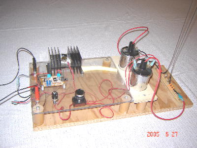
This is our Jacobs Ladder project. It utilizes a 555 timer circuit and transistor to fire two automotive ignition coils. The ladder rods can be seen on the far right.
The unit is powered by a 12 volt transformer and rectifier bridge to provide 12 vdc. A 2200 uF capacitor is across the DC input to provide filter capacitance and reduce ripple.
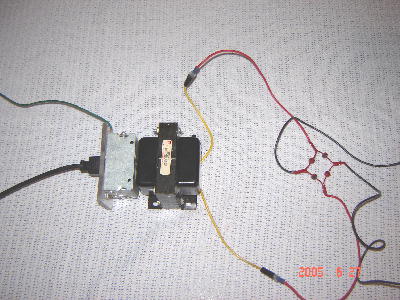
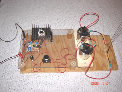
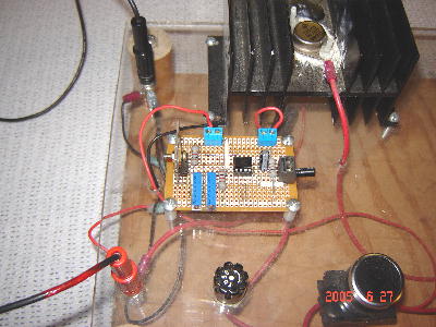
The (2) ignition coils are located on the right side of this view. The 555 timer and its control circuit are on the left. The transistor is mounted on a heat sink in the back. We used a 7805 voltage regulator on the 555 timer board to give a stable voltage source. The ignition coils run directly from the 12 vdc input(after an inline fuse and push button).
The timer board has an astable 555 timer circuit with potentiometers to adjust
Ra and Rb. We have a pair of terminals for C1 so we can change its value.
For our coils, we found Ra = 3650 ohms, Rb = 995 ohms, and C1 = 0.1 uF(1E-07 Farads) to
give the best performance. This gives a theoretical timer frequency of 2550 hz.
(Note Corrected Data 2-28-06)
Frequency = 1.44/((Ra + 2*Rb)*C1) where C1 in Farads and Ra, Rb in Ohms
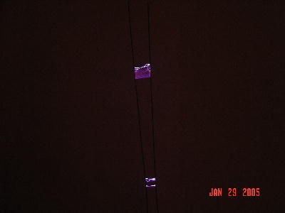
The photo below shows a climbing arc. Pictures don't do this project justice. You have to see it live to appreciate it.
Click Here for Ignition Coil Driver Schematic*
* Viewing this gif file is poor on the Internet. Save to your computer and view with gif viewer.
Click Here to return to TeslaBoys Home Page